Part (3.1) DCNM and VXLAN BGP and EVPN Lab with Nexus 9000v Overview
In this update we outline the virtual lab topology used as the sandbox to explore APIs and Visualisations with Grafana and DCNM. If you already have a DCNM environment available, you can skip this page and continue to Part 3.2.
3.1.2 Resources
- DCNM REST API Reference Guide
- Easy Provisioning of VXLAN BGP EVPN Fabrics
- Auto-Provisioning Border Gateways with Multi-Site Domains
- VXLAN EVPN Multi-Site Design and Deployment Whitepaper
- Cisco Communities - Data Center
3.1.2.1 Cisco Modelling Labs, GNS3 and EVE-NG Deployment Guides
3.1.3 DCNM VXLAN BGP and EVPN Lab Overview
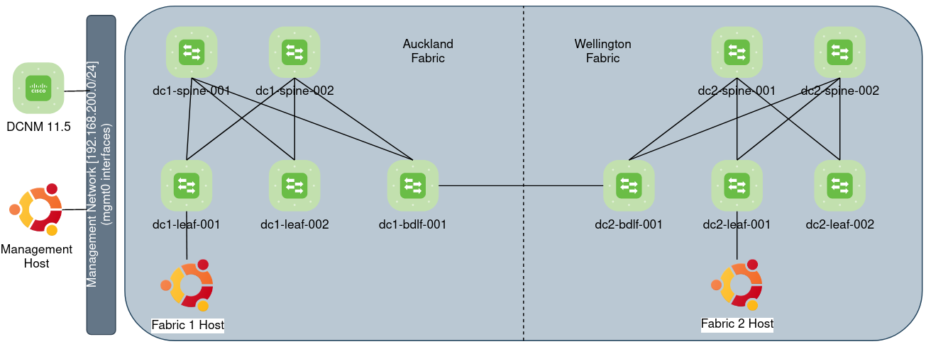
The Lab includes the following:
- 2 x Fabrics Auckland and Wellington, each fabric has:
- 2 x spines
- 2 x leafs
- 1 x Border Gateway for DCI between Fabrics
- 1 x ubuntu guest - connected to a leaf switch in each fabrics
- 1 x ubuntu guest connected to the management network
3.1.3.1 DCNM VXLAN BGP and EVPN Lab Virtual Appliances
| Appliance | Image name | Version | Memory | CPU | Disk | Qty |
|---|---|---|---|---|---|---|
| DCNM | dcnm-va.11.5.1.iso | 11.5 | 24768MB | 8vCPUs | 100G | 1 |
| n9000v | nexus9300v.9.3.7.qcow2 | 9.3.7 | 8096MB | 2vCPUs | - | 10 |
| Ubuntu Desktop | Ubuntu 20.10 (64bit).vmdk | 20.10 | 1024MB | 1vCPUs | - | 3 |
Note: DCNM minimum requirements are exactly that, requirements If CPU, Disk or memory for DCNM is under-provisioned, you’ll be redirected to https://[DCNM-IP]:2443/resourceerror.html. Shutdown the DCNM virtual-machine and assign the minimum virtual machine requirements as above.
3.1.4 Considerations
Note the following pre-requisites from the MSD configuration guide:
- The underlay IP addresses across the fabrics, the loopback 0 address and the loopback 1 address subnets should be unique.
- Ensure that each fabric has a unique IP address pool to avoid duplicates.
- Each fabric should have a unique site ID and BGP AS number associated and configured.
- All fabrics should have the same Anycast Gateway MAC address.
3.1.5 Base Configuration
Configure the hostname, management address and boot image for each device:
conf t
interface mgmt 0
  ip address [192.168.200.229/24]
!
ip route 0.0.0.0 0.0.0.0 [192.168.200.1] vrf management
hostname [dc2-bdlf-001]
boot nxos bootflash:///nxos.9.3.7.bin
copy run st
Note – With a DHCP assigned address on Mgmt0, you might encounter - “Error during configuration read or intent” error when Saving and Deploying configuration. Statically assigned IP addresses to Mgmt0 should resolve.
3.1.6 Site 1 “Auckland Fabric” Deployment and the Easy_Fabric template
From the Control menu, select Fabric Builder, Create Fabric, name the fabric and provide a BGP ASN 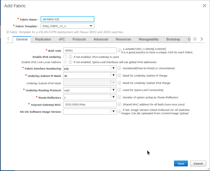
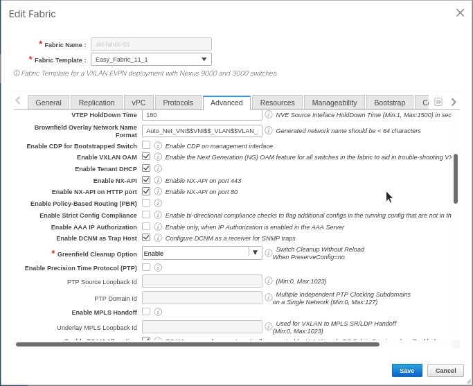
We’re using N9000v’s for our lab, Under advanced “Greenfield Cleanup” – select “enable”
From the configuration guide: “Greenfield Cleanup Option – Enable the switch cleanup option for switches imported into DCNM with Preserve-Config=No, without a switch reload. This option is typically recommended only for the fabric environments with Cisco Nexus 9000v Switches to improve on the switch clean up time.
On the Resources tab – either accept defaults for the first fabric, or if connecting multiple sites, note the IP and VNI ranges as these will need to be unique to each site.
Defaults are fine for Manageability , Bootstrap, Configuration Backup tabs
3.1.6.1 Add switches to Site 1 “Auckland Fabric”
Management address, username and password define in base configuration 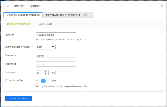
Select manageable switches and Import to Fabric 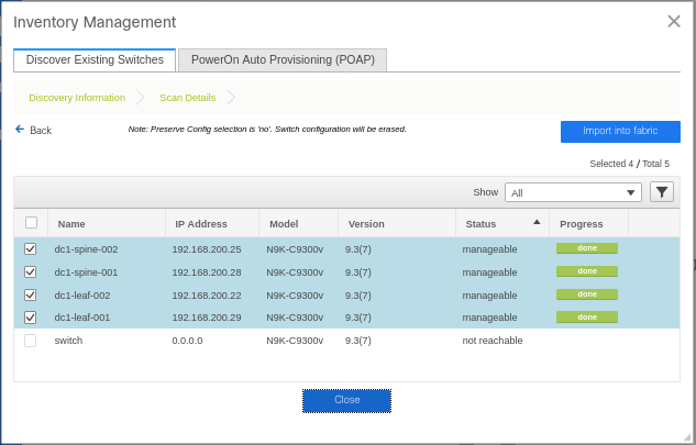
Right click on spines and set roles, in my case I also have a border leaf that I added after the initial deployment, click “Save and Deploy” 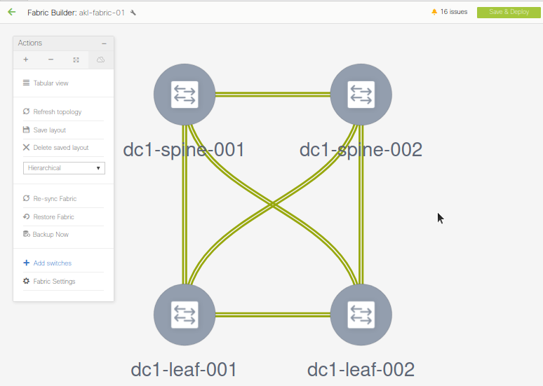
Deploy the Configuration 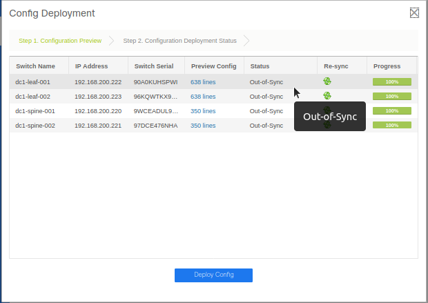
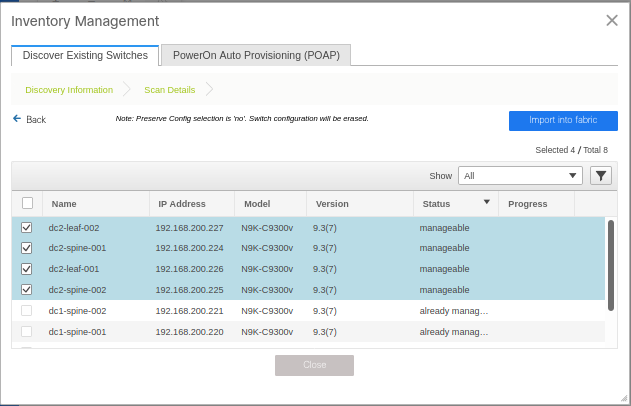
3.1.7 Site 2 “Wellington Fabric” Deployment and the Easy_Fabric template
Create the fabric for the second site, defining unique subnet ranges and BGP ASNs as described in the pre-requisites
Define the spine and Border Gateway Roles as required and Deploy Config - site two should now be In Sync 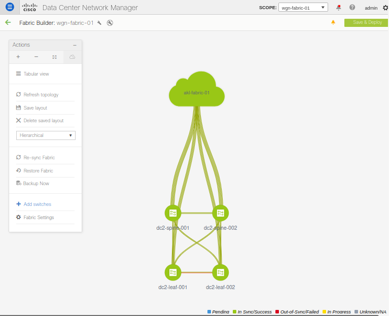
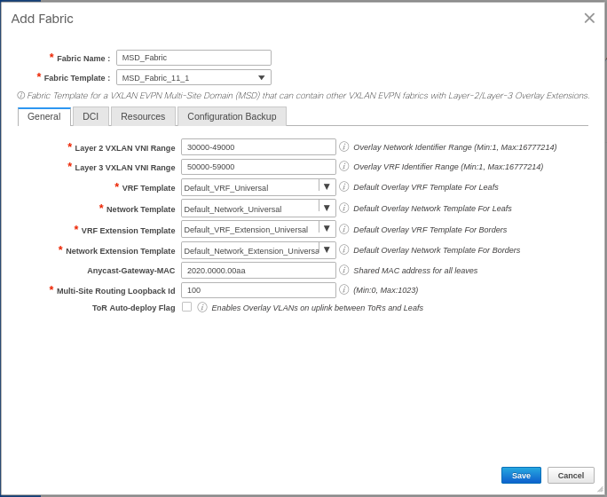
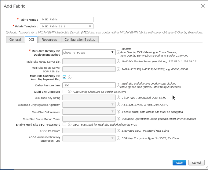
3.1.8 Multi-Site Domain (MSD) Deployment
To interconnect our two VXLAN EVPN fabrics together, we’ll use DCNM’s Multi-Site feature and MSD_Fabric template. This will provision the configuration required to deploy Datacenter interconnect (DCI) overlays to the border gateway switches (BGWs) defined previously.
The MSD feature will be the control point for overlay networks that are stretched between fabrics
3.1.8.1 Fabric Definition
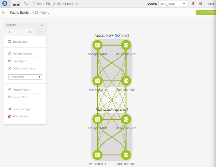
3.1.8.2 Fabric Members and Operational State
Click the tabular view to see a summarised table of all switches in the MSD Fabric: 
3.1.9 Verification
The design guide outlines verification commands for VTEPs, fabric and DCI links and the EVPN control-plane and VXLAN data plane:
3.1.9.1 Features
dc1-leaf-001# show feature | grep enabled | exclude "not-run"
bgp                    1          enabled
dhcp                   1          enabled
hmm                    1          enabled
icam                   1          enabled
interface-vlan         1          enabled
lacp                   1          enabled
lldp                   1          enabled
ngoam                  1          enabled
nve                    1          enabled
nxapi                  1          enabled
ospf                   1          enabled
pim                    1          enabled
sshServer              1          enabled
vnseg_vlan             1          enabled
vpc                    1          enabled
3.1.9.2 NVE interface
dc1-leaf-001# show nve interface nve 1 detail
Interface: nve1, State: Up, encapsulation: VXLAN
 VPC Capability: VPC-VIP-Only [notified]
 Local Router MAC: 0c44.b700.1b08
 Host Learning Mode: Control-Plane
 Source-Interface: loopback1 (primary: 10.3.0.3, secondary: 10.3.0.1)
 Source Interface State: Up
 Virtual RMAC Advertisement: No
 NVE Flags:
 Interface Handle: 0x49000001
 Source Interface hold-down-time: 180
 Source Interface hold-up-time: 30
 Remaining hold-down time: 0 seconds
 Virtual Router MAC: 0200.0a03.0001
 Interface state: nve-intf-add-complete
3.1.9.3 vPC
 dc1-leaf-001# show vpc brief
 Legend:
                 (*) - local vPC is down, forwarding via vPC peer-link

 vPC domain id                     : 1
 Peer status                       : peer adjacency formed ok
 vPC keep-alive status             : peer is alive
 Configuration consistency status  : success
 Per-vlan consistency status       : success
 Type-2 consistency status         : success
 vPC role                          : primary
 Number of vPCs configured         : 0
 Peer Gateway                      : Enabled
 Dual-active excluded VLANs        : -
 Graceful Consistency Check        : Enabled
 Auto-recovery status              : Enabled, timer is off.(timeout = 360s)
 Delay-restore status              : Timer is off.(timeout = 150s)
 Delay-restore SVI status          : Timer is off.(timeout = 10s)
 Operational Layer3 Peer-router    : Disabled
 Virtual-peerlink mode             : Disabled

 vPC Peer-link status
 ---------------------------------------------------------------------
 id    Port   Status Active vlans
 --    ----   ------ -------------------------------------------------
 1     Po500  up     1,3600
3.1.9.4 BGP
dc1-spine-002# show bgp l2vpn evpn summary vrf all
BGP summary information for VRF default, address family L2VPN EVPN
BGP router identifier 10.2.0.4, local AS number 65001
BGP table version is 13, L2VPN EVPN config peers 3, capable peers 3
1 network entries and 1 paths using 244 bytes of memory
BGP attribute entries [1/172], BGP AS path entries [0/0]
BGP community entries [0/0], BGP clusterlist entries [0/0]

Neighbor        V    AS MsgRcvd MsgSent   TblVer  InQ OutQ Up/Down  State/PfxRcd
10.2.0.1        4 65001    2491    2491       13    0    0    1d17h 0
10.2.0.2        4 65001    2491    2491       13    0    0    1d17h 0
10.2.0.5        4 65001    1696    1698       13    0    0 17:45:00 1
3.1.9.5 EVPN Fabric links
dc1-bdlf-001# show nve multisite fabric-links
Interface      State
---------      -----
Ethernet1/1    Up
Ethernet1/2    Up
3.1.9.6 EVPN DCI Links
dc1-bdlf-001# show nve multisite dci-links
Interface      State
---------      -----
Ethernet1/3    Up
3.1.9.7 Designated Forwaders
dc1-bdlf-001# show nve multisite fabric-links
Interface      State
---------      -----
Ethernet1/1    Up
Ethernet1/2    Up

dc1-bdlf-001# show nve e
ethernet-segment   evi
dc1-bdlf-001# show nve ethernet-segment

ESI: 0300.0000.00fd.e900.0309
   Parent interface: nve1
  ES State: Up
  Port-channel state: N/A
  NVE Interface: nve1
   NVE State: Up
   Host Learning Mode: control-plane
  Active Vlans: 1
   DF Vlans: 1
   Active VNIs: \
  CC failed for VLANs:
  VLAN CC timer: no-timer
  Number of ES members: 1
  My ordinal: 0
  DF timer start time: 00:00:00
  Config State: N/A
  DF List: 10.3.0.2
  ES route added to L2RIB: True
  EAD/ES routes added to L2RIB: False
  EAD/EVI route timer age: not running
----------------------------------------
3.1.10 Wrap Up
This ends the overview of DCNM Virtual Lab setup. We’ll look into DCNM APIs and Dashboards in the next update, Building a DCNM Dashboard with Grafana, Django and Python.